
|
|
||||||||||||||||||||||||||||||
| Code | ||||||||||||||||||||||||||||||
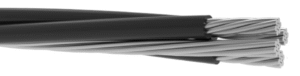
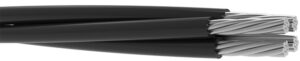
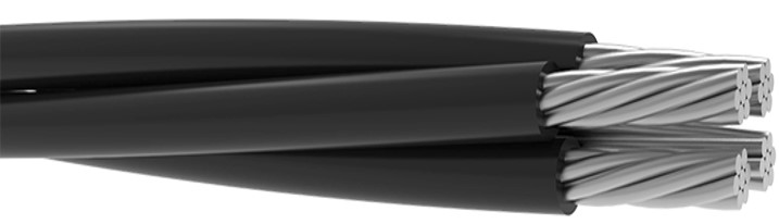
| ABC | ||||||||||||||||||||||||||||||
| Voltage Rating | ||||||||||||||||||||||||||||||
| 0.6/1 kV | ||||||||||||||||||||||||||||||
| Standards | ||||||||||||||||||||||||||||||
| NF C 33-209 & SI 1740 | ||||||||||||||||||||||||||||||
| Conductor | ||||||||||||||||||||||||||||||
| Stranded Aluminium Conductor | ||||||||||||||||||||||||||||||
| Insulation: | ||||||||||||||||||||||||||||||
| XLPE (Cross Linked Polyethylene) | ||||||||||||||||||||||||||||||
| Construction | ||||||||||||||||||||||||||||||
| 1 core: Straıght (marking) | ||||||||||||||||||||||||||||||
| 2 core: Straıght (marking) – 1 Notch or number | ||||||||||||||||||||||||||||||
| 3 core: Straıght (marking) – 1 Notch or number – 2 Notch or number | ||||||||||||||||||||||||||||||
| 4 core: Straıght (marking) – 1 Notch or number – 2 Notch or number – 3 Notch or number | ||||||||||||||||||||||||||||||
| 5 core: Straıght (marking) – 1 Notch or number – 2 Notch or number – 3 Notch or number – EP1 Straıght | ||||||||||||||||||||||||||||||
| 5 core: Straıght (marking) – 1 Notch or number – 2 Notch or number – 3 Notch or number – 4 Notch or number | ||||||||||||||||||||||||||||||
| 6 core: Straıght (marking) – 1 Notch or number – 2 Notch or number – 3 Notch or number – EP1 Straıght – EP2 1 Notch | ||||||||||||||||||||||||||||||
| 6 core:1 Notch or number – 2 Notch or number – 3 Notch or number – 4 Notch or marking – EP1 Straıght – EP2 1 Notch | ||||||||||||||||||||||||||||||
| Technical Data | ||||||||||||||||||||||||||||||
| Max. Operating Temperature | : | 90°C | ||||||||||||||||||||||||||||
| Short Circuit Temperature | : | 250°C (max.5 sec) | ||||||||||||||||||||||||||||
| Operating Temperature | : | -40°C to +80°C | ||||||||||||||||||||||||||||
| Bending Radius | : | 12xD | ||||||||||||||||||||||||||||
| Test Voltage | : | 4.0 kV | ||||||||||||||||||||||||||||
| Application: | ||||||||||||||||||||||||||||||
| Aerial Bundle Cable (ABC) low voltage cable for overhead power distribution offering higher level of safety and | ||||||||||||||||||||||||||||||
| reliability and lower power losses than bare conductors. | ||||||||||||||||||||||||||||||
| INSULATED WIRES | MESSENGER | FINISHED CABLE | ||||||||||||||||||||||||||||
| Phase Conductor | Main Distrubition Line | |||||||||||||||||||||||||||||
| Nominal Cross Section | Cross Section | Dia.of Conductor | Resistance at 20°C | Current Carrying Capacity | Cross Section | Resistance at 20°C |
Dia.of Conductor | Min.Tensile Strenght |
Resistance at 20°C |
Diameter Of Cable | Net Weight | |||||||||||||||||||
| mm² | mm² | mm | ohm/km | A | mm² | ohm/km | mm | kN | ohm/km | mm | kg/km | |||||||||||||||||||
| 1×10 | 10 | 3,7 | 3,08 | – | – | – | – | – | – | 5,7 | 47,0 | |||||||||||||||||||
| 1×16 | 16 | 4,7 | 1,91 | – | – | – | – | – | – | 7,1 | 66,0 | |||||||||||||||||||
| 1×25 | 25 | 5,9 | 1,20 | – | – | – | – | – | – | 8,7 | 101,2 | |||||||||||||||||||
| 1×35 | 35 | 6,9 | 0,868 | – | – | – | – | – | – | 10,1 | 137,0 | |||||||||||||||||||
| 1×50 | 50 | 8,1 | 0,641 | – | – | – | – | – | – | 11,3 | 176,0 | |||||||||||||||||||
| 1×70 | 70 | 10,0 | 0,443 | – | – | – | – | – | – | 13,6 | 245,6 | |||||||||||||||||||
| 1×95 | 95 | 11,5 | 0,320 | – | – | – | – | – | – | 15,1 | 318,0 | |||||||||||||||||||
| 1×120 | 120 | 12,8 | 0,253 | – | – | – | – | – | – | 16,4 | 388,5 | |||||||||||||||||||
| 1×150 | 150 | 14,8 | 0,206 | – | – | – | – | – | – | 18,2 | 478,0 | |||||||||||||||||||
| 2×16 | 16 | 4,7 | 1,91 | – | – | – | – | – | – | 14,2 | 133,6 | |||||||||||||||||||
| 2×25 | 25 | 5,9 | 1,20 | – | – | – | – | – | – | 17,3 | 204,8 | |||||||||||||||||||
| 2×35 | 35 | 6,9 | 0,868 | – | – | – | – | – | – | 20,2 | 277,3 | |||||||||||||||||||
| 2×50 | 50 | 8,1 | 0,641 | – | – | – | – | – | – | 22,6 | 356,2 | |||||||||||||||||||
| 2×70 | 70 | 10,0 | 0,443 | – | – | – | – | – | – | 27,2 | 497,1 | |||||||||||||||||||
| 2×95 | 95 | 11,5 | 0,320 | – | – | – | – | – | – | 30,2 | 643,6 | |||||||||||||||||||
| 2×120 | 120 | 12,8 | 0,253 | – | – | – | – | – | – | 32,9 | 786,3 | |||||||||||||||||||
| 3×70 | 70 | 10,0 | 0,443 | – | – | – | – | – | – | 29,3 | 746,6 | |||||||||||||||||||
| 3×95 | 95 | 11,5 | 0,320 | – | – | – | – | – | – | 32,6 | 966,6 | |||||||||||||||||||
| 4×10 | 10 | 3,7 | 3,08 | – | – | – | – | – | – | 13,8 | 189,5 | |||||||||||||||||||
| 4×16 | 16 | 4,7 | 1,91 | – | – | – | – | – | – | 17,2 | 267,7 | |||||||||||||||||||
| 4×25 | 25 | 5,9 | 1,20 | – | – | – | – | – | – | 21,0 | 410,5 | |||||||||||||||||||
| 4×35 | 35 | 6,9 | 0,868 | – | – | – | – | – | – | 24,4 | 555,7 | |||||||||||||||||||
| 4×50 | 50 | 8,1 | 0,641 | – | – | – | – | – | – | 27,3 | 713,9 | |||||||||||||||||||
| 4×70 | 70 | 10,0 | 0,443 | – | – | – | – | – | – | 32,9 | 996,2 | |||||||||||||||||||
| 4×95 | 95 | 11,5 | 0,320 | – | – | – | – | – | – | 36,5 | 1289,8 | |||||||||||||||||||
| 4×120 | 120 | 12,8 | 0,253 | – | – | – | – | – | – | 39,8 | 1575,8 | |||||||||||||||||||
| 5×16 | 16 | 4,7 | 1,91 | – | – | – | – | – | – | 19,1 | 335,0 | |||||||||||||||||||
| 5×25 | 25 | 5,9 | 1,20 | – | – | – | – | – | – | 23,4 | 513,6 | |||||||||||||||||||
| 5×35 | 35 | 6,9 | 0,868 | – | – | – | – | – | – | 27,2 | 695,3 | |||||||||||||||||||
| 5×70 | 70 | 10,0 | 0,443 | – | – | – | – | – | – | 36,7 | 1246,4 | |||||||||||||||||||
| 6×16 | 16 | 4,7 | 1,91 | – | – | – | – | – | – | 21,2 | 402,3 | |||||||||||||||||||
| 6×25 | 25 | 5,9 | 1,20 | – | – | – | – | – | – | 25,9 | 616,9 | |||||||||||||||||||
| INSULATED WIRES | MESSENGER | FINISHED CABLE | ||||||||||||||||||||||||||||
| Phase Conductor | Main Distrubition Line | |||||||||||||||||||||||||||||
| Nominal Cross Section | Cross Section | Dia.of Conductor | Resistance at 20°C | Current Carrying Capacity | Cross Section | Resistance at 20°C |
Dia.of Conductor | Min.Tensile Strenght |
Resistance at 20°C |
Diameter Of Cable | Net Weight | |||||||||||||||||||
| mm² | mm² | mm | ohm/km | A | mm² | ohm/km | mm | kN | ohm/km | mm | kg/km | |||||||||||||||||||
| 3×16+25 | 16 | 4,7 | 1,91 | – | – | – | 5,9 | – | 1,20 | 18,1 | 303,6 | |||||||||||||||||||
| 3×16+54,6 | 16 | 4,7 | 1,91 | – | – | – | 9,5 | – | 0,630 | 20,5 | 420,0 | |||||||||||||||||||
| 3×25+25 | 16 | 5,9 | 1,20 | – | – | – | 6,3 | – | 1,38 | 21,2 | 410,4 | |||||||||||||||||||
| 3×25+35 | 25 | 5,9 | 1,20 | – | – | – | 6,9 | – | 0,868 | 21,8 | 446,8 | |||||||||||||||||||
| 3×25+54,6 | 25 | 5,9 | 1,20 | – | – | – | 9,5 | – | 0,630 | 23,4 | 526,9 | |||||||||||||||||||
| 3×35+50 | 35 | 6,9 | 0,868 | – | – | – | 8,1 | – | 0,641 | 25,1 | 595,2 | |||||||||||||||||||
| 3×35+54,6 | 35 | 6,9 | 0,868 | – | – | – | 9,5 | – | 0,630 | 26,0 | 635,8 | |||||||||||||||||||
| 3×50+35 | 50 | 8,1 | 0,641 | – | – | – | 6,9 | – | 0,868 | 26,6 | 674,3 | |||||||||||||||||||
| 3×50+54,6 | 50 | 8,1 | 0,641 | – | – | – | 9,5 | – | 0,630 | 28,2 | 754,4 | |||||||||||||||||||
| 3×50+70 | 50 | 8,1 | 0,641 | – | – | – | 10,5 | – | 0,500 | 28,7 | 789,5 | |||||||||||||||||||
| 3×70+54,6 | 70 | 10,0 | 0,443 | – | – | – | 9,5 | – | 0,630 | 32,3 | 966,2 | |||||||||||||||||||
| 3×70+95 | 70 | 10,0 | 0,443 | – | – | – | 12,4 | – | 0,343 | 35,1 | 1069,6 | |||||||||||||||||||
| 3×95+54,6 | 95 | 11,5 | 0,320 | – | – | – | 9,5 | – | 0,630 | 35,0 | 1186,4 | |||||||||||||||||||
| 3×95+70 | 95 | 11,5 | 0,320 | – | – | – | 10,5 | – | 0,500 | 35,6 | 1221,4 | |||||||||||||||||||
| 3×95+95 | 95 | 11,5 | 0,320 | – | – | – | 12,4 | – | 0,343 | 36,8 | 1302,6 | |||||||||||||||||||
| 3×120+70 | 120 | 12,8 | 0,253 | – | – | – | 10,5 | – | 0,500 | 38,0 | 1437,2 | |||||||||||||||||||
| 3×120+95 | 120 | 12,8 | 0,253 | – | – | – | 12,4 | – | 0,343 | 40,9 | 1517,1 | |||||||||||||||||||
| 3×150+70 | 150 | 14,8 | 0,206 | – | – | – | 10,5 | – | 0,500 | 41,2 | 1708,2 | |||||||||||||||||||
| 3×150+95 | 150 | 14,8 | 0,206 | – | – | – | 12,4 | – | 0,343 | 42,5 | 1792,3 | |||||||||||||||||||
| 4×25+35 | 25 | 5,9 | 1,20 | – | – | – | 6,9 | – | 0,868 | 24,2 | 549,9 | |||||||||||||||||||
| 4×35+16 | 35 | 6,9 | 0,868 | – | – | – | 4,7 | – | 1,91 | 25,6 | 623,4 | |||||||||||||||||||
| 4×70+16 | 70 | 10,0 | 0,443 | – | – | – | 4,7 | – | 1,91 | 33,2 | 1064,4 | |||||||||||||||||||
| INSULATED WIRES | MESSENGER | FINISHED CABLE | ||||||||||||||||||||||||||||
| Phase Conductor | Main Distrubition Line | |||||||||||||||||||||||||||||
| Nominal Cross Section | Cross Section | Dia.of Conductor | Resistance at 20°C | Current Carrying Capacity | Cross Section | Resistance at 20°C |
Dia.of Conductor | Min.Tensile Strenght |
Resistance at 20°C |
Diameter Of Cable | Net Weight | |||||||||||||||||||
| mm² | mm² | mm | ohm/km | A | mm² | ohm/km | mm | kN | ohm/km | mm | kg/km | |||||||||||||||||||
| 3×25+54,6+1×16 | 25 | 5,9 | 1,20 | – | 16 | 1,91 | 9,5 | – | 0,630 | 24,7 | 594,4 | |||||||||||||||||||
| 3×35+50+1×16 | 35 | 6,9 | 0,868 | – | 16 | 1,91 | 8,1 | – | 0,641 | 26,3 | 667,6 | |||||||||||||||||||
| 3×35+54,6+1×16 | 35 | 6,9 | 0,868 | – | 16 | 1,91 | 9,5 | – | 0,630 | 27,0 | 703,4 | |||||||||||||||||||
| 3×35+54,6+1×25 | 35 | 6,9 | 0,868 | – | 25 | 1,20 | 9,5 | – | 0,630 | 27,9 | 739,2 | |||||||||||||||||||
| 3×50+54,6+1×16 | 50 | 8,1 | 0,641 | – | 16 | 1,91 | 9,5 | – | 0,630 | 29,0 | 822,0 | |||||||||||||||||||
| 3×50+70+1×25 | 50 | 8,1 | 0,641 | – | 25 | 1,20 | 10,5 | – | 0,500 | 30,3 | 893,0 | |||||||||||||||||||
| 3×70+54,6+1×16 | 70 | 10,0 | 0,443 | – | 16 | 1,91 | 9,5 | – | 0,630 | 32,7 | 1033,9 | |||||||||||||||||||
| 3×70+95+1×25 | 70 | 10,0 | 0,443 | – | 25 | 1,20 | 12,4 | – | 0,343 | 34,1 | 1186,2 | |||||||||||||||||||
| 3×95+54,6+1×16 | 95 | 11,5 | 0,320 | – | 16 | 1,91 | 9,5 | – | 0,630 | 35,1 | 1254,6 | |||||||||||||||||||
| 3×95+70+1×16 | 95 | 11,5 | 0,320 | – | 16 | 1,91 | 10,5 | – | 0,500 | 35,6 | 1289,9 | |||||||||||||||||||
| 3×150+70+1×16 | 150 | 14,8 | 0,206 | – | 16 | 1,91 | 10,5 | – | 0,500 | 40,6 | 1778,6 | |||||||||||||||||||
| 3×25+54,6+2×16 | 25 | 5,9 | 1,20 | – | 16 | 1,91 | 9,5 | – | 0,630 | 26,3 | 662,0 | |||||||||||||||||||
| 3×25+54,6+2×25 | 25 | 5,9 | 1,20 | – | 25 | 1,20 | 9,5 | – | 0,630 | 27,9 | 733,4 | |||||||||||||||||||
| 3×35+54,6+2×16 | 35 | 6,9 | 0,868 | – | 16 | 1,91 | 9,5 | – | 0,630 | 28,5 | 771,3 | |||||||||||||||||||
| 3×35+54,6+2×25 | 35 | 6,9 | 0,868 | – | 25 | 1,20 | 9,5 | – | 0,630 | 30,0 | 842,7 | |||||||||||||||||||
| 3×50+54,6+2×16 | 50 | 8,1 | 0,641 | – | 16 | 1,91 | 9,5 | – | 0,630 | 30,3 | 890,0 | |||||||||||||||||||
| 3×50+54,6+2×25 | 50 | 8,1 | 0,641 | – | 25 | 1,20 | 9,5 | – | 0,630 | 31,8 | 961,4 | |||||||||||||||||||
| 3×70+54,6+2×16 | 70 | 10,0 | 0,443 | – | 16 | 1,91 | 9,5 | – | 0,630 | 33,7 | 1102,2 | |||||||||||||||||||
| 3×70+54,6+2×25 | 70 | 10,0 | 0,443 | – | 25 | 1,20 | 9,5 | – | 0,630 | 35,2 | 1173,6 | |||||||||||||||||||
| 3×95+50+2×25 | 95 | 11,5 | 0,320 | – | 25 | 1,20 | 8,1 | – | 0,641 | 36,8 | 1357,9 | |||||||||||||||||||
| 3×95+54,6+2×16 | 95 | 11,5 | 0,320 | – | 16 | 1,91 | 9,5 | – | 0,630 | 35,9 | 1322,9 | |||||||||||||||||||
| 3×95+54,6+2×25 | 95 | 11,5 | 0,320 | – | 25 | 1,20 | 9,5 | – | 0,630 | 37,5 | 1394,3 | |||||||||||||||||||
| 3×120+95+2×25 | 120 | 12,8 | 0,253 | – | 25 | 1,20 | 12,4 | – | 0,343 | 39,2 | 1725,6 | |||||||||||||||||||
| 3×150+70+2×16 | 150 | 14,8 | 0,206 | – | 16 | 1,91 | 10,5 | – | 0,500 | 41,0 | 1845,8 | |||||||||||||||||||
| 3×150+95+2×25 | 150 | 14,8 | 0,206 | – | 25 | 1,20 | 12,4 | – | 0,343 | 43,6 | 1998,6 | |||||||||||||||||||
| 4×70+54,6+1×16 | 70 | 10,0 | 0,443 | – | 16 | 1,91 | 9,5 | – | 0,630 | 36,9 | 1284,7 | |||||||||||||||||||
| INSULATED WIRES | MESSENGER | FINISHED CABLE | ||||||||||||||||||||||||||||
| Phase Conductor | Main Distrubition Line | |||||||||||||||||||||||||||||
| Nominal Cross Section | Cross Section | Dia.of Conductor | Resistance at 20°C | Current Carrying Capacity | Cross Section | Resistance at 20°C |
Dia.of Conductor | Min.Tensile Strenght |
Resistance at 20°C |
Diameter Of Cable | Net Weight | |||||||||||||||||||
| mm² | mm² | mm | ohm/km | A | mm² | ohm/km | mm | kN | ohm/km | mm | kg/km | |||||||||||||||||||
| 4×25+2×16 | 25 | 5,9 | 1,20 | – | 16 | 1,91 | – | – | – | 24,7 | 545,2 | |||||||||||||||||||
| 4×25+2×25 | 25 | 5,9 | 1,20 | – | 25 | 1,20 | – | – | – | 25,9 | 616,3 | |||||||||||||||||||
| 4×35+2×16 | 35 | 6,9 | 0,868 | – | 16 | 1,91 | – | – | – | 27,2 | 690,4 | |||||||||||||||||||
| 4×35+2×25 | 35 | 6,9 | 0,868 | – | 25 | 1,20 | – | – | – | 27,7 | 761,9 | |||||||||||||||||||
| 4×50+2×16 | 50 | 8,1 | 0,641 | – | 16 | 1,91 | – | – | – | 29,6 | 849,3 | |||||||||||||||||||
| 4×50+2×25 | 50 | 8,1 | 0,641 | – | 25 | 1,20 | – | – | – | 31,1 | 920,7 | |||||||||||||||||||
| 4×70+2×16 | 70 | 10,0 | 0,443 | – | 16 | 1,91 | – | – | – | 34,1 | 1132,2 | |||||||||||||||||||
| 4×70+2×25 | 70 | 10,0 | 0,443 | – | 25 | 1,20 | – | – | – | 35,7 | 1203,6 | |||||||||||||||||||
| 4×95+2×16 | 95 | 11,5 | 0,320 | – | 16 | 1,91 | – | – | – | 37,1 | 1426,5 | |||||||||||||||||||
| 4×95+2×25 | 95 | 11,5 | 0,320 | – | 25 | 1,20 | – | – | – | 38,7 | 1497,9 | |||||||||||||||||||
| 4×150+2×25 | 150 | 14,8 | 0,206 | – | 25 | 1,20 | – | – | – | 45,0 | 2148,4 | |||||||||||||||||||
| Note1: | ||||||||||||||||||||||||||||||
| The vein colors mentioned above may vary according to customer demand. | ||||||||||||||||||||||||||||||
| Note2: | ||||||||||||||||||||||||||||||
| Current carrying capacities are valid at 30°C ambient temperature. | ||||||||||||||||||||||||||||||