
|
|
||||||||||||||||||||||||||||||||||||||||||||||||||
| Code | ||||||||||||||||||||||||||||||||||||||||||||||||||
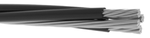
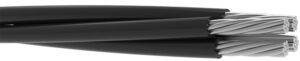
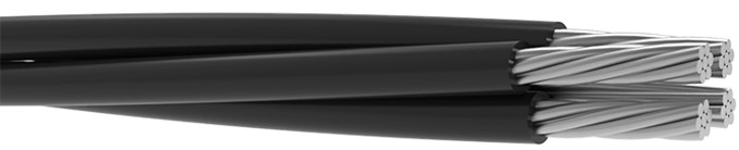
| ABC | ||||||||||||||||||||||||||||||||||||||||||||||||||
| Voltage Rating | ||||||||||||||||||||||||||||||||||||||||||||||||||
| 0.6/1 kV | ||||||||||||||||||||||||||||||||||||||||||||||||||
| Standards | ||||||||||||||||||||||||||||||||||||||||||||||||||
| HD 626 S1 | ||||||||||||||||||||||||||||||||||||||||||||||||||
| Conductor | ||||||||||||||||||||||||||||||||||||||||||||||||||
| Stranded Aluminium Conductor | ||||||||||||||||||||||||||||||||||||||||||||||||||
| Insulation: | ||||||||||||||||||||||||||||||||||||||||||||||||||
| XLPE (Cross Linked Polyethylene) | ||||||||||||||||||||||||||||||||||||||||||||||||||
| Construction | ||||||||||||||||||||||||||||||||||||||||||||||||||
| 1 core: Straıght (marking) | ||||||||||||||||||||||||||||||||||||||||||||||||||
| 2 core: Straıght (marking) – 1 Notch or number | ||||||||||||||||||||||||||||||||||||||||||||||||||
| 3 core: Straıght (marking) – 1 Notch or number – 2 Notch or number | ||||||||||||||||||||||||||||||||||||||||||||||||||
| 4 core: Straıght (marking) – 1 Notch or number – 2 Notch or number – 3 Notch or number | ||||||||||||||||||||||||||||||||||||||||||||||||||
| 5 core: Straıght (marking) – 1 Notch or number – 2 Notch or number – 3 Notch or number – EP1 Straıght | ||||||||||||||||||||||||||||||||||||||||||||||||||
| 5 core: Straıght (marking) – 1 Notch or number – 2 Notch or number – 3 Notch or number – 4 Notch or number | ||||||||||||||||||||||||||||||||||||||||||||||||||
| 6 core: Straıght (marking) – 1 Notch or number – 2 Notch or number – 3 Notch or number – EP1 Straıght – EP2 1 Notch | ||||||||||||||||||||||||||||||||||||||||||||||||||
| 6 core:1 Notch or number – 2 Notch or number – 3 Notch or number – 4 Notch or marking – EP1 Straıght – EP2 1 Notch | ||||||||||||||||||||||||||||||||||||||||||||||||||
| Technical Data | ||||||||||||||||||||||||||||||||||||||||||||||||||
| Max. Operating Temperature | : | 90°C | ||||||||||||||||||||||||||||||||||||||||||||||||
| Short Circuit Temperature | : | 250°C (max.5 sec) | ||||||||||||||||||||||||||||||||||||||||||||||||
| Operating Temperature | : | -40°C to +80°C | ||||||||||||||||||||||||||||||||||||||||||||||||
| Bending Radius | : | 12xD | ||||||||||||||||||||||||||||||||||||||||||||||||
| Test Voltage | : | 4.0 kV | ||||||||||||||||||||||||||||||||||||||||||||||||
| Application: | ||||||||||||||||||||||||||||||||||||||||||||||||||
| Aerial Bundle Cable (ABC) low voltage cable for overhead power distribution offering higher level of safety and | ||||||||||||||||||||||||||||||||||||||||||||||||||
| reliability and lower power losses than bare conductors. | ||||||||||||||||||||||||||||||||||||||||||||||||||
|
|
||||||||||||||||||||||||||||||||||||||||||||||||||
| INSULATED WIRES | MESSENGER | FINISHED CABLE | ||||||||||||||||||||||||||||||||||||||||||||||||
| Phase Conductor | Main Distrubition Line | |||||||||||||||||||||||||||||||||||||||||||||||||
| Nominal Cross Section | Cross Section | Dia.of Conductor | Resistance at 20°C | Current Carrying Capacity | Cross Section | Resistance at 20°C |
Dia.of Conductor | Min.Tensile Strenght |
Resistance at 20°C |
Diameter Of Cable | Net Weight | |||||||||||||||||||||||||||||||||||||||
| mm² | mm² | mm | ohm/km | A | mm² | ohm/km | mm | kN | ohm/km | mm | kg/km | |||||||||||||||||||||||||||||||||||||||
| 1×10 | 10 | 3,7 | 3,08 | – | – | – | – | – | – | 5,7 | 42,8 | |||||||||||||||||||||||||||||||||||||||
| 1×16 | 16 | 4,7 | 1,91 | – | – | – | – | – | – | 7,1 | 65,0 | |||||||||||||||||||||||||||||||||||||||
| 1×25 | 25 | 5,9 | 1,20 | – | – | – | – | – | – | 8,5 | 98,7 | |||||||||||||||||||||||||||||||||||||||
| 1×35 | 35 | 6,9 | 0,868 | – | – | – | – | – | – | 9,5 | 129,5 | |||||||||||||||||||||||||||||||||||||||
| 1×50 | 50 | 8,1 | 0,641 | – | – | – | – | – | – | 11,1 | 173,3 | |||||||||||||||||||||||||||||||||||||||
| 1×63 | 63 | 9,7 | 0,456 | – | – | – | – | – | – | 12,7 | 230,2 | |||||||||||||||||||||||||||||||||||||||
| 1×70 | 70 | 10,0 | 0,443 | – | – | – | – | – | – | 13,0 | 238,6 | |||||||||||||||||||||||||||||||||||||||
| 1×95 | 95 | 11,5 | 0,320 | – | – | – | – | – | – | 14,9 | 314,3 | |||||||||||||||||||||||||||||||||||||||
| 1×120 | 120 | 12,8 | 0,253 | – | – | – | – | – | – | 16,2 | 384,5 | |||||||||||||||||||||||||||||||||||||||
| 1×150 | 150 | 14,8 | 0,206 | – | – | – | – | – | – | 18,2 | 478,0 | |||||||||||||||||||||||||||||||||||||||
| 1×185 | 185 | 16,6 | 0,164 | – | – | – | – | – | – | 20,2 | 617,2 | |||||||||||||||||||||||||||||||||||||||
| 1×240 | 240 | 18,8 | 0,125 | – | – | – | – | – | – | 22,8 | 781,2 | |||||||||||||||||||||||||||||||||||||||
| 1×300 | 300 | 21,2 | 0,100 | – | – | – | – | – | – | 25,6 | 991,7 | |||||||||||||||||||||||||||||||||||||||
| 1×400 | 400 | 24,1 | 0,0778 | – | – | – | – | – | – | 28,5 | 1295,8 | |||||||||||||||||||||||||||||||||||||||
| 1×500 | 500 | 27,2 | 0,0605 | – | – | – | – | – | – | 32,0 | 1614,0 | |||||||||||||||||||||||||||||||||||||||
| 2×10 | 10 | 3,7 | 3,08 | – | – | – | – | – | – | 11,4 | 86,6 | |||||||||||||||||||||||||||||||||||||||
| 2×16 | 16 | 4,7 | 1,91 | – | – | – | – | – | – | 14,2 | 131,6 | |||||||||||||||||||||||||||||||||||||||
| 2×25 | 25 | 5,9 | 1,20 | – | – | – | – | – | – | 16,9 | 199,8 | |||||||||||||||||||||||||||||||||||||||
| 2×35 | 35 | 6,9 | 0,868 | – | – | – | – | – | – | 19,0 | 263,6 | |||||||||||||||||||||||||||||||||||||||
| 2×50 | 50 | 8,1 | 0,641 | – | – | – | – | – | – | 22,2 | 350,7 | |||||||||||||||||||||||||||||||||||||||
| 2×70 | 70 | 10,0 | 0,443 | – | – | – | – | – | – | 26,0 | 482,9 | |||||||||||||||||||||||||||||||||||||||
| 2×95 | 95 | 11,5 | 0,320 | – | – | – | – | – | – | 29,8 | 636,1 | |||||||||||||||||||||||||||||||||||||||
| 2×120 | 120 | 12,8 | 0,253 | – | – | – | – | – | – | 32,5 | 778,2 | |||||||||||||||||||||||||||||||||||||||
| 3×10 | 10 | 3,7 | 3,08 | – | – | – | – | – | – | 12,3 | 130,4 | |||||||||||||||||||||||||||||||||||||||
| 3×16 | 16 | 4,7 | 1,91 | – | – | – | – | – | – | 15,3 | 199,4 | |||||||||||||||||||||||||||||||||||||||
| 3×25 | 25 | 5,9 | 1,20 | – | – | – | – | – | – | 18,3 | 301,7 | |||||||||||||||||||||||||||||||||||||||
| 3×35 | 35 | 6,9 | 0,868 | – | 20,5 | 396,6 | ||||||||||||||||||||||||||||||||||||||||||||
| 3×50 | 50 | 8,1 | 0,641 | – | – | – | – | – | – | 24,0 | 526,7 | |||||||||||||||||||||||||||||||||||||||
| 3×70 | 70 | 10,0 | 0,443 | – | – | – | – | – | – | 28,0 | 725,3 | |||||||||||||||||||||||||||||||||||||||
| 3×95 | 95 | 11,5 | 0,320 | – | – | – | – | – | – | 32,2 | 955,4 | |||||||||||||||||||||||||||||||||||||||
| 3×120 | 120 | 12,8 | 0,253 | – | – | – | – | – | – | 35,1 | 1168,7 | |||||||||||||||||||||||||||||||||||||||
| 4×10 | 10 | 3,7 | 3,08 | – | – | – | – | – | – | 13,8 | 173,9 | |||||||||||||||||||||||||||||||||||||||
| 4×16 | 16 | 4,7 | 1,91 | – | – | – | – | – | – | 17,2 | 266,0 | |||||||||||||||||||||||||||||||||||||||
| 4×25 | 25 | 5,9 | 1,20 | – | – | – | – | – | – | 20,5 | 402,5 | |||||||||||||||||||||||||||||||||||||||
| 4×35 | 35 | 6,9 | 0,868 | – | – | – | – | – | – | 23,0 | 529,2 | |||||||||||||||||||||||||||||||||||||||
| 4×50 | 50 | 8,1 | 0,641 | – | – | – | – | – | – | 26,8 | 702,7 | |||||||||||||||||||||||||||||||||||||||
| 4×70 | 70 | 10,0 | 0,443 | – | – | – | – | – | – | 31,4 | 967,8 | |||||||||||||||||||||||||||||||||||||||
| 4×95 | 95 | 11,5 | 0,320 | – | – | – | – | – | – | 36,0 | 1274,8 | |||||||||||||||||||||||||||||||||||||||
| 4×120 | 120 | 12,8 | 0,253 | – | – | – | – | – | – | 39,3 | 1559,5 | |||||||||||||||||||||||||||||||||||||||
| 4×150 | 150 | 14,8 | 0,206 | – | – | – | – | – | – | 44,1 | 1938,8 | |||||||||||||||||||||||||||||||||||||||
| 4×185 | 185 | 16,6 | 0,164 | – | – | – | – | – | – | 48,8 | 2503,5 | |||||||||||||||||||||||||||||||||||||||
| 4×240 | 240 | 18,8 | 0,125 | – | – | – | – | – | – | 55,1 | 3168,6 | |||||||||||||||||||||||||||||||||||||||
| 5×10 | 10 | 3,7 | 3,08 | – | – | – | – | – | – | 15,4 | 217,5 | |||||||||||||||||||||||||||||||||||||||
| 5×16 | 16 | 4,7 | 1,91 | – | – | – | – | – | – | 19,1 | 332,7 | |||||||||||||||||||||||||||||||||||||||
| 5×25 | 25 | 5,9 | 1,20 | – | – | – | – | – | – | 22,8 | 503,4 | |||||||||||||||||||||||||||||||||||||||
| 5×35 | 35 | 6,9 | 0,868 | – | – | – | – | – | – | 25,6 | 662,0 | |||||||||||||||||||||||||||||||||||||||
| 6×10 | 10 | 3,7 | 3,08 | – | – | – | – | – | – | 17,1 | 261,2 | |||||||||||||||||||||||||||||||||||||||
| 6×16 | 16 | 4,7 | 1,91 | – | – | – | – | – | – | 21,2 | 399,5 | |||||||||||||||||||||||||||||||||||||||
| 6×25 | 25 | 5,9 | 1,20 | – | – | – | – | – | – | 25,3 | 604,5 | |||||||||||||||||||||||||||||||||||||||
| INSULATED WIRES | MESSENGER | FINISHED CABLE | ||||||||||||||||||||||||||||||||||||||||||||||||
| Phase Conductor | Main Distrubition Line | |||||||||||||||||||||||||||||||||||||||||||||||||
| Nominal Cross Section | Cross Section | Dia.of Conductor | Resistance at 20°C | Current Carrying Capacity | Cross Section | Resistance at 20°C |
Dia.of Conductor | Min.Tensile Strenght |
Resistance at 20°C |
Diameter Of Cable | Net Weight | |||||||||||||||||||||||||||||||||||||||
| mm² | mm² | mm | ohm/km | A | mm² | ohm/km | mm | kN | ohm/km | mm | kg/km | |||||||||||||||||||||||||||||||||||||||
| 3×16+25 | 16 | 4,7 | 1,91 | – | – | – | 6,3 | – | 1,38 | 18,3 | 300,5 | |||||||||||||||||||||||||||||||||||||||
| 3×16+54,6 | 16 | 4,7 | 1,91 | – | – | – | 9,5 | – | 0,630 | 20,4 | 415,1 | |||||||||||||||||||||||||||||||||||||||
| 3×25+16 | 16 | 5,9 | 1,20 | – | – | – | 4,7 | – | 1,91 | 19,6 | 368,4 | |||||||||||||||||||||||||||||||||||||||
| 3×25+35 | 25 | 5,9 | 1,20 | – | – | – | 7,4 | – | 0,986 | 21,4 | 433,9 | |||||||||||||||||||||||||||||||||||||||
| 3×25+54,6 | 25 | 5,9 | 1,20 | – | – | – | 9,5 | – | 0,630 | 22,9 | 517,5 | |||||||||||||||||||||||||||||||||||||||
| 3×35+16 | 35 | 6,9 | 0,868 | – | – | – | 4,7 | – | 1,91 | 23,0 | 463,4 | |||||||||||||||||||||||||||||||||||||||
| 3×35+50 | 35 | 6,9 | 0,868 | – | – | – | 8,7 | – | 0,720 | 24,3 | 571,9 | |||||||||||||||||||||||||||||||||||||||
| 3×35+54,6 | 35 | 6,9 | 0,868 | – | – | – | 9,5 | – | 0,630 | 24,8 | 612,5 | |||||||||||||||||||||||||||||||||||||||
| 3×35+70 | 35 | 6,9 | 0,868 | – | – | – | 10,5 | – | 0,500 | 25,6 | 661,6 | |||||||||||||||||||||||||||||||||||||||
| 3×50+25 | 50 | 8,1 | 0,641 | – | – | – | 6,3 | – | 1,38 | 25,5 | 628,7 | |||||||||||||||||||||||||||||||||||||||
| 3×50+35 | 50 | 8,1 | 0,641 | – | – | – | 7,4 | – | 0,986 | 26,2 | 659,1 | |||||||||||||||||||||||||||||||||||||||
| 3×50+54,6 | 50 | 8,1 | 0,641 | – | – | – | 9,5 | – | 0,630 | 27,7 | 742,6 | |||||||||||||||||||||||||||||||||||||||
| 3×50+70 | 50 | 8,1 | 0,641 | – | – | – | 10,5 | – | 0,500 | 28,5 | 791,8 | |||||||||||||||||||||||||||||||||||||||
| 3×70+35 | 70 | 10,0 | 0,443 | – | – | – | 7,4 | – | 0,986 | 29,6 | 857,9 | |||||||||||||||||||||||||||||||||||||||
| 3×70+50 | 70 | 10,0 | 0,443 | – | – | – | 8,7 | – | 0,720 | 30,6 | 905,8 | |||||||||||||||||||||||||||||||||||||||
| 3×70+54,6 | 70 | 10,0 | 0,443 | – | – | – | 9,5 | – | 0,630 | 31,1 | 941,4 | |||||||||||||||||||||||||||||||||||||||
| 3×70+70 | 70 | 10,0 | 0,443 | – | – | – | 10,5 | – | 0,500 | 32,0 | 990,6 | |||||||||||||||||||||||||||||||||||||||
| 3×70+95 | 70 | 10,0 | 0,443 | – | – | – | 12,4 | – | 0,343 | 33,1 | 1066,4 | |||||||||||||||||||||||||||||||||||||||
| 3×95+50 | 95 | 11,5 | 0,320 | – | – | – | 8,7 | – | 0,720 | 34,1 | 1131,8 | |||||||||||||||||||||||||||||||||||||||
| 3×95+54,6 | 95 | 11,5 | 0,320 | – | – | – | 9,5 | – | 0,630 | 34,6 | 1171,7 | |||||||||||||||||||||||||||||||||||||||
| 3×95+70 | 95 | 11,5 | 0,320 | – | – | – | 10,5 | – | 0,500 | 35,4 | 1220,8 | |||||||||||||||||||||||||||||||||||||||
| 3×95+95 | 95 | 11,5 | 0,320 | – | – | – | 12,4 | – | 0,343 | 36,6 | 1296,6 | |||||||||||||||||||||||||||||||||||||||
| 3×120+70 | 120 | 12,8 | 0,253 | – | – | – | 10,5 | – | 0,500 | 37,9 | 1435,4 | |||||||||||||||||||||||||||||||||||||||
| 3×120+95 | 120 | 12,8 | 0,253 | – | – | – | 12,4 | – | 0,343 | 39,0 | 1510,2 | |||||||||||||||||||||||||||||||||||||||
| 3×150+70 | 150 | 14,8 | 0,206 | – | – | – | 10,5 | – | 0,500 | 41,5 | 1718,8 | |||||||||||||||||||||||||||||||||||||||
| 3×150+95 | 150 | 14,8 | 0,206 | – | – | – | 12,4 | – | 0,343 | 42,6 | 1797,6 | |||||||||||||||||||||||||||||||||||||||
| 3×240+120 | 240 | 18,8 | 0,125 | – | – | – | 12,8 | – | 0,253 | 51,1 | 2766,3 | |||||||||||||||||||||||||||||||||||||||
| 4×25+16 | 25 | 5,9 | 1,20 | – | – | – | 4,7 | – | 1,91 | 22,1 | 469,3 | |||||||||||||||||||||||||||||||||||||||
| 4×25+35 | 25 | 5,9 | 1,20 | – | – | – | 6,9 | – | 0,868 | 23,7 | 534,9 | |||||||||||||||||||||||||||||||||||||||
| 4×35+16 | 35 | 6,9 | 0,868 | – | – | – | 4,7 | – | 1,91 | 24,3 | 596,1 | |||||||||||||||||||||||||||||||||||||||
| 4×35+25 | 35 | 6,9 | 0,868 | – | – | – | 5,9 | – | 1,20 | 25,1 | 630,3 | |||||||||||||||||||||||||||||||||||||||
| 4×50+25 | 50 | 8,1 | 0,641 | – | – | – | 5,9 | – | 1,20 | 28,8 | 804,8 | |||||||||||||||||||||||||||||||||||||||
| 4×95+25 | 95 | 11,5 | 0,320 | – | – | – | 5,9 | – | 1,20 | 37,0 | 1377,9 | |||||||||||||||||||||||||||||||||||||||
| INSULATED WIRES | MESSENGER | FINISHED CABLE | ||||||||||||||||||||||||||||||||||||||||||||||||
| Phase Conductor | Main Distrubition Line | |||||||||||||||||||||||||||||||||||||||||||||||||
| Nominal Cross Section | Cross Section | Dia.of Conductor | Resistance at 20°C | Current Carrying Capacity | Cross Section | Resistance at 20°C |
Dia.of Conductor | Min.Tensile Strenght |
Resistance at 20°C |
Diameter Of Cable | Net Weight | |||||||||||||||||||||||||||||||||||||||
| mm² | mm² | mm | ohm/km | A | mm² | ohm/km | mm | kN | ohm/km | mm | kg/km | |||||||||||||||||||||||||||||||||||||||
| 3×25+54,6+1×16 | 25 | 5,9 | 1,20 | – | 16 | 1,91 | 9,5 | – | 0,630 | 24,3 | 584,4 | |||||||||||||||||||||||||||||||||||||||
| 3×35+50+1×16 | 35 | 6,9 | 0,868 | – | 16 | 1,91 | 8,7 | – | 0,720 | 25,5 | 643,3 | |||||||||||||||||||||||||||||||||||||||
| 3×35+54,6+1×16 | 35 | 6,9 | 0,868 | – | 16 | 1,91 | 9,5 | – | 0,630 | 25,9 | 679,5 | |||||||||||||||||||||||||||||||||||||||
| 3×35+54,6+1×25 | 35 | 6,9 | 0,868 | – | 25 | 1,20 | 9,5 | – | 0,630 | 26,7 | 713,7 | |||||||||||||||||||||||||||||||||||||||
| 3×50+25+1×16 | 50 | 8,1 | 0,641 | – | 16 | 1,91 | 6,3 | – | 1,38 | 26,6 | 695,2 | |||||||||||||||||||||||||||||||||||||||
| 3×50+35+1×25 | 50 | 8,1 | 0,641 | – | 25 | 1,20 | 7,4 | – | 0,986 | 27,9 | 760,3 | |||||||||||||||||||||||||||||||||||||||
| 3×50+54,6+1×16 | 50 | 8,1 | 0,641 | – | 16 | 1,91 | 9,5 | – | 0,630 | 28,5 | 809,8 | |||||||||||||||||||||||||||||||||||||||
| 3×50+70+1×25 | 50 | 8,1 | 0,641 | – | 25 | 1,20 | 10,5 | – | 0,500 | 30,0 | 893,4 | |||||||||||||||||||||||||||||||||||||||
| 3×70+35+1×16 | 70 | 10,0 | 0,443 | – | 16 | 1,91 | 7,4 | – | 0,986 | 30,3 | 925,2 | |||||||||||||||||||||||||||||||||||||||
| 3×70+50+35 | 70 | 10,0 | 0,443 | – | 35 | 0,868 | 8,7 | – | 0,720 | 32,5 | 1038,0 | |||||||||||||||||||||||||||||||||||||||
| 3×70+54,6+1×16 | 70 | 10,0 | 0,443 | – | 16 | 1,91 | 9,5 | – | 0,630 | 31,6 | 1008,7 | |||||||||||||||||||||||||||||||||||||||
| 3×70+95+1×25 | 70 | 10,0 | 0,443 | – | 25 | 1,20 | 12,4 | – | 0,343 | 34,1 | 1168,9 | |||||||||||||||||||||||||||||||||||||||
| 3×95+50+1×16 | 95 | 11,5 | 0,320 | – | 16 | 1,91 | 8,7 | – | 0,720 | 34,3 | 1203,8 | |||||||||||||||||||||||||||||||||||||||
| 3×95+54,6+1×16 | 95 | 11,5 | 0,320 | – | 16 | 1,91 | 9,5 | – | 0,630 | 34,7 | 1239,4 | |||||||||||||||||||||||||||||||||||||||
| 3×95+70+50 | 95 | 11,5 | 0,320 | – | 50 | 0,641 | 10,5 | – | 0,500 | 37,5 | 1396,7 | |||||||||||||||||||||||||||||||||||||||
| 3×120+70+1×16 | 120 | 12,8 | 0,253 | – | 16 | 1,91 | 10,5 | – | 0,500 | 37,9 | 1501,9 | |||||||||||||||||||||||||||||||||||||||
| 3×120+95+70 | 120 | 12,8 | 0,253 | – | 70 | 0,443 | 12,4 | – | 0,343 | 41,8 | 1751,8 | |||||||||||||||||||||||||||||||||||||||
| 3×25+54,6+2×16 | 25 | 5,9 | 1,20 | – | 16 | 1,91 | 9,5 | – | 0,630 | 25,9 | 651,3 | |||||||||||||||||||||||||||||||||||||||
| 3×25+54,6+2×25 | 25 | 5,9 | 1,20 | – | 25 | 1,20 | 9,5 | – | 0,630 | 27,3 | 719,5 | |||||||||||||||||||||||||||||||||||||||
| 3×35+54,6+2×16 | 35 | 6,9 | 0,868 | – | 16 | 1,91 | 9,5 | – | 0,630 | 27,5 | 746,8 | |||||||||||||||||||||||||||||||||||||||
| 3×35+54,6+2×25 | 35 | 6,9 | 0,868 | – | 25 | 1,20 | 9,5 | – | 0,630 | 28,8 | 815,0 | |||||||||||||||||||||||||||||||||||||||
| 3×35+70+2×16 | 35 | 6,9 | 0,868 | – | 16 | 1,91 | 10,5 | – | 0,500 | 28,2 | 795,4 | |||||||||||||||||||||||||||||||||||||||
| 3×50+54,6+2×16 | 50 | 8,1 | 0,641 | – | 16 | 1,91 | 9,5 | – | 0,630 | 29,9 | 877,2 | |||||||||||||||||||||||||||||||||||||||
| 3×50+54,6+2×25 | 50 | 8,1 | 0,641 | – | 25 | 1,20 | 9,5 | – | 0,630 | 31,2 | 945,4 | |||||||||||||||||||||||||||||||||||||||
| 3×70+54,6+2×16 | 70 | 10,0 | 0,443 | – | 16 | 1,91 | 9,5 | – | 0,630 | 32,7 | 1076,5 | |||||||||||||||||||||||||||||||||||||||
| 3×70+54,6+2×25 | 70 | 10,0 | 0,443 | – | 25 | 1,20 | 9,5 | – | 0,630 | 34,0 | 1144,7 | |||||||||||||||||||||||||||||||||||||||
| 3×70+70+2×16 | 70 | 10,0 | 0,443 | – | 16 | 1,91 | 10,5 | – | 0,500 | 33,4 | 1125,7 | |||||||||||||||||||||||||||||||||||||||
| 3×70+70+2×25 | 70 | 10,0 | 0,443 | – | 25 | 1,20 | 10,5 | – | 0,500 | 34,8 | 1194,6 | |||||||||||||||||||||||||||||||||||||||
| 3×95+50+2×25 | 95 | 11,5 | 0,320 | – | 25 | 1,20 | 8,7 | – | 0,720 | 36,5 | 1339,7 | |||||||||||||||||||||||||||||||||||||||
| 3×95+54,6+2×16 | 95 | 11,5 | 0,320 | – | 16 | 1,91 | 9,5 | – | 0,630 | 35,5 | 1307,2 | |||||||||||||||||||||||||||||||||||||||
| 3×95+54,6+2×25 | 95 | 11,5 | 0,320 | – | 25 | 1,20 | 9,5 | – | 0,630 | 36,9 | 1375,4 | |||||||||||||||||||||||||||||||||||||||
| 3×120+95+2×25 | 120 | 12,8 | 0,253 | – | 25 | 1,20 | 12,4 | – | 0,343 | 40,5 | 1714,5 | |||||||||||||||||||||||||||||||||||||||
| 3×150+95+2×25 | 150 | 14,8 | 0,206 | – | 25 | 1,20 | 12,4 | – | 0,343 | 43,5 | 1999,7 | |||||||||||||||||||||||||||||||||||||||
| INSULATED WIRES | MESSENGER | FINISHED CABLE | ||||||||||||||||||||||||||||||||||||||||||||||||
| Phase Conductor | Main Distrubition Line | |||||||||||||||||||||||||||||||||||||||||||||||||
| Nominal Cross Section | Cross Section | Dia.of Conductor | Resistance at 20°C | Current Carrying Capacity | Cross Section | Resistance at 20°C |
Dia.of Conductor | Min.Tensile Strenght |
Resistance at 20°C |
Diameter Of Cable | Net Weight | |||||||||||||||||||||||||||||||||||||||
| mm² | mm² | mm | ohm/km | A | mm² | ohm/km | mm | kN | ohm/km | mm | kg/km | |||||||||||||||||||||||||||||||||||||||
| 4×25+2×16 | 25 | 5,9 | 1,20 | – | 16 | 1,91 | – | – | – | 23,9 | 536 | |||||||||||||||||||||||||||||||||||||||
| 4×25+2×25 | 25 | 5,9 | 1,20 | – | 25 | 1,20 | – | – | – | 25,3 | 604,5 | |||||||||||||||||||||||||||||||||||||||
| 4×35+2×16 | 35 | 6,9 | 0,868 | – | 16 | 1,91 | – | – | – | 26,0 | 662,7 | |||||||||||||||||||||||||||||||||||||||
| 4×35+2×25 | 35 | 6,9 | 0,868 | – | 25 | 1,20 | – | – | – | 27,4 | 730,9 | |||||||||||||||||||||||||||||||||||||||
| 4×50+2×16 | 50 | 8,1 | 0,641 | – | 16 | 1,91 | – | – | – | 29,2 | 837,2 | |||||||||||||||||||||||||||||||||||||||
| 4×50+2×25 | 50 | 8,1 | 0,641 | – | 25 | 1,20 | – | – | – | 30,5 | 905,4 | |||||||||||||||||||||||||||||||||||||||
| 4×70+2×16 | 70 | 10,0 | 0,443 | – | 16 | 1,91 | – | – | – | 32,9 | 1102,8 | |||||||||||||||||||||||||||||||||||||||
| 4×70+2×25 | 70 | 10,0 | 0,443 | – | 25 | 1,20 | – | – | – | 34,3 | 1171 | |||||||||||||||||||||||||||||||||||||||
| 4×95+2×16 | 95 | 11,5 | 0,320 | – | 16 | 1,91 | – | – | – | 36,7 | 1410,5 | |||||||||||||||||||||||||||||||||||||||
| 4×95+2×25 | 95 | 11,5 | 0,320 | – | 25 | 1,20 | – | – | – | 38,1 | 1478,7 | |||||||||||||||||||||||||||||||||||||||
| Note1: | ||||||||||||||||||||||||||||||||||||||||||||||||||
| The vein colors mentioned above may vary according to customer demand. | ||||||||||||||||||||||||||||||||||||||||||||||||||
| Note2: | ||||||||||||||||||||||||||||||||||||||||||||||||||
| Current carrying capacities are valid at 30°C ambient temperature. | ||||||||||||||||||||||||||||||||||||||||||||||||||