|
|
|||||||||||||||||||
| Code | |||||||||||||||||||
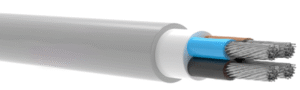
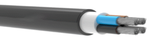
| A2X2Y-AF AL/XLPE/PVC/HDPE | |||||||||||||||||||
| Voltage Rating | |||||||||||||||||||
| 0.6/1 kV AC – 1000 / 1800 V DC | |||||||||||||||||||
| Standards | |||||||||||||||||||
| IEC 60228 | Conductor | ||||||||||||||||||
| EN 61034 | Smoke Density | ||||||||||||||||||
| EN 50267 | Halogen Free | ||||||||||||||||||
| EN 60332-3 | Flame Retardant (Cat C) | ||||||||||||||||||
| Reaction to Fire Classification ( CPR ) | |||||||||||||||||||
| EN 60332-1-2 | Flame Retardant | ||||||||||||||||||
| Conductor | |||||||||||||||||||
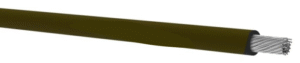
| Flexible Aluminum Conductor (Class 5) | |||||||||||||||||||
| Insulation | |||||||||||||||||||
| XLPE (Cross-linked Polyethylene) | |||||||||||||||||||
| Filler | |||||||||||||||||||
| PVC Filler | |||||||||||||||||||
| Armour | |||||||||||||||||||
| – | |||||||||||||||||||
| Sheath | |||||||||||||||||||
| HDPE (High Density Polyethylene) – UV Resistance | |||||||||||||||||||
| Waterproof ACC. AD8 | |||||||||||||||||||
| Technical Data | |||||||||||||||||||
| Max. Operating Temperature | : | 90°C | |||||||||||||||||
| Short Circuit Temperature | : | 250°C (max.5 sec) | |||||||||||||||||
| Bending Radius | : | 6D ( D : Overall Diameter ) | |||||||||||||||||
| Test Voltage | : | 3,5 kV | |||||||||||||||||
| Application: | |||||||||||||||||||
| For installation indoors and outdoors, in cable ducts, underground , in power or switching stations,local energy | |||||||||||||||||||
| distributions, industrial plants, where there is no risk of mechanical damage.Suitable for comparatively high | |||||||||||||||||||
| maximum permissible conductor temperature. | |||||||||||||||||||
| Nominal Cross Section | Overall Diameter | Net Weight | Delivery Length | Resistance at 20°C | Current Carrying Capacity | ||||||||||||||
| (mm²) | (mm) | (kg/km) | (m) | (ohm/km) | In Ground at 20°C | In Air at 30°C | |||||||||||||
| 1×1,5* | 6,9 | 47,6 | 1000 | 19,25 | – | – | |||||||||||||
| 1×2,5* | 7,4 | 55,0 | 1000 | 11,55 | – | – | |||||||||||||
| 1×4* | 8,0 | 66,1 | 1000 | 7,22 | – | – | |||||||||||||
| 1×6* | 8,3 | 76,8 | 1000 | 4,81 | – | – | |||||||||||||
| 1×10 | 9,6 | 100,5 | 1000 | 3,08 | – | – | |||||||||||||
| 1×16 | 10,4 | 125,0 | 1000 | 1,91 | – | – | |||||||||||||
| 1×25 | 12,5 | 178,1 | 1000 | 1,20 | 114 | 106 | |||||||||||||
| 1×35 | 13,5 | 216,7 | 1000 | 0,868 | 136 | 130 | |||||||||||||
| 1×50 | 14,7 | 268,9 | 1000 | 0,641 | 162 | 161 | |||||||||||||
| 1×70 | 16,9 | 352,2 | 1000 | 0,443 | 199 | 204 | |||||||||||||
| 1×95 | 18,8 | 447,0 | 1000 | 0,320 | 238 | 252 | |||||||||||||
| 1×120 | 21,3 | 558,6 | 1000 | 0,253 | 272 | 295 | |||||||||||||
| 1×150 | 23,0 | 674,2 | 1000 | 0,206 | 305 | 339 | |||||||||||||
| 1×185 | 25,7 | 829,3 | 1000 | 0,164 | 347 | 395 | |||||||||||||
| 1×240 | 28,7 | 1056,7 | 1000 | 0,125 | 404 | 472 | |||||||||||||
| 1×300 | 31,7 | 1305,0 | 1000 | 0,100 | 457 | 547 | |||||||||||||
| 1×400 | 35,2 | 1644,2 | 500 | 0,0778 | 525 | 643 | |||||||||||||
| 1×500 | 40,2 | 2080,8 | 500 | 0,0605 | 601 | 754 | |||||||||||||
| 1×630 | 44,1 | 2573,8 | 500 | 0,0469 | 687 | 882 | |||||||||||||
| Nominal Cross Section | Overall Diameter | Net Weight | Delivery Length | Resistance at 20°C | Current Carrying Capacity | ||||||||||||||
| (mm²) | (mm) | (kg/km) | (m) | (ohm/km) | In Ground at 20°C | In Air at 30°C | |||||||||||||
| 2×1,5* | 10,4 | 118,7 | 1000 | 19,25 | – | – | |||||||||||||
| 2×2,5* | 11,3 | 142,8 | 1000 | 11,55 | – | – | |||||||||||||
| 2×4* | 12,6 | 179,8 | 1000 | 7,22 | – | – | |||||||||||||
| 2×6* | 13,5 | 221,1 | 1000 | 4,81 | – | – | |||||||||||||
| 2×10 | 15,8 | 298,0 | 1000 | 3,08 | – | – | |||||||||||||
| 2×16 | 17,5 | 377,9 | 1000 | 1,91 | – | – | |||||||||||||
| 2×25 | 21,5 | 576,0 | 1000 | 1,20 | 112 | 102 | |||||||||||||
| 2×35 | 23,8 | 722,0 | 1000 | 0,868 | 135 | 126 | |||||||||||||
| 2×50 | 26,3 | 916,6 | 1000 | 0,641 | 158 | 149 | |||||||||||||
| 2×70 | 30,9 | 1237,8 | 1000 | 0,443 | 196 | 191 | |||||||||||||
| 2×95 | 35,0 | 1586,0 | 1000 | 0,320 | 234 | 234 | |||||||||||||
| 2×120 | 39,3 | 2015,7 | 1000 | 0,253 | 268 | 273 | |||||||||||||
| 2×150 | 43,0 | 2449,4 | 1000 | 0,206 | 300 | 311 | |||||||||||||
| 2×185 | 48,2 | 3047,2 | 500 | 0,164 | 342 | 360 | |||||||||||||
| 2×240 | 54,3 | 3906,2 | 500 | 0,125 | 398 | 427 | |||||||||||||
| Nominal Cross Section | Overall Diameter | Net Weight | Delivery Length | Resistance at 20°C | Current Carrying Capacity | ||||||||||||||
| (mm²) | (mm) | (kg/km) | (m) | (ohm/km) | In Ground at 20°C | In Air at 30°C | |||||||||||||
| 3×1,5* | 10,9 | 128,4 | 1000 | 19,25 | – | – | |||||||||||||
| 3×2,5* | 11,8 | 155,8 | 1000 | 11,55 | – | – | |||||||||||||
| 3×4* | 13,2 | 197,6 | 1000 | 7,22 | – | – | |||||||||||||
| 3×6* | 14,2 | 245,2 | 1000 | 4,81 | – | – | |||||||||||||
| 3×10 | 16,7 | 332,3 | 1000 | 3,08 | – | – | |||||||||||||
| 3×16 | 18,5 | 427,0 | 1000 | 1,91 | – | – | |||||||||||||
| 3×25 | 22,9 | 651,2 | 1000 | 1,20 | 112 | 102 | |||||||||||||
| 3×35 | 25,3 | 821,5 | 1000 | 0,868 | 135 | 126 | |||||||||||||
| 3×50 | 28,1 | 1059,8 | 1000 | 0,641 | 158 | 149 | |||||||||||||
| 3×70 | 33,2 | 1424,5 | 1000 | 0,443 | 196 | 191 | |||||||||||||
| 3×95 | 37,5 | 1839,9 | 1000 | 0,320 | 234 | 234 | |||||||||||||
| 3×120 | 42,2 | 2317,0 | 1000 | 0,253 | 268 | 273 | |||||||||||||
| 3×150 | 46,3 | 2827,9 | 1000 | 0,206 | 300 | 311 | |||||||||||||
| 3×185 | 51,8 | 3526,9 | 500 | 0,164 | 342 | 360 | |||||||||||||
| 3×240 | 58,6 | 4530,0 | 500 | 0,125 | 398 | 427 | |||||||||||||
| 3×300 | 64,4 | 5616,3 | 500 | 0,100 | 457 | 507 | |||||||||||||
| 3×400 | 72,5 | 7151,1 | 250 | 0,0778 | 529 | 600 | |||||||||||||
| Nominal Cross Section | Overall Diameter | Net Weight | Delivery Length | Resistance at 20°C | Current Carrying Capacity | ||||||||||||||
| (mm²) | (mm) | (kg/km) | (m) | (ohm/km) | In Ground at 20°C | In Air at 30°C | |||||||||||||
| 3×16+10 | 19,7 | 482,6 | 1000 | 1,91 – 3,08 | – | – | |||||||||||||
| 3×25+16 | 23,9 | 712,6 | 1000 | 1,20 – 1,91 | 112 | 102 | |||||||||||||
| 3×35+16 | 25,9 | 864,7 | 1000 | 0,868 – 1,91 | 135 | 126 | |||||||||||||
| 3×50+25 | 29,4 | 1156,2 | 1000 | 0,641 – 1,20 | 158 | 149 | |||||||||||||
| 3×70+35 | 34,6 | 1548,1 | 1000 | 0,443 – 0,868 | 196 | 191 | |||||||||||||
| 3×95+50 | 39,0 | 1997,1 | 1000 | 0,320 – 0,641 | 234 | 234 | |||||||||||||
| 3×120+70 | 44,3 | 2570,1 | 500 | 0,253 – 0,443 | 268 | 273 | |||||||||||||
| 3×150+70 | 47,7 | 3025,9 | 500 | 0,206 – 0,443 | 300 | 311 | |||||||||||||
| 3×185+95 | 53,7 | 3785,6 | 500 | 0,164 – 0,320 | 342 | 360 | |||||||||||||
| 3×240+120 | 60,4 | 4859,8 | 500 | 0,125 – 0,253 | 398 | 427 | |||||||||||||
| 3×300+150 | 66,6 | 5965,5 | 250 | 0,100 – 0,206 | 457 | 507 | |||||||||||||
| 3×400+185 | 74,8 | 7537,2 | 250 | 0,0778 – 0,164 | 529 | 600 | |||||||||||||
| Nominal Cross Section | Overall Diameter | Net Weight | Delivery Length | Resistance at 20°C | Current Carrying Capacity | ||||||||||||||
| (mm²) | (mm) | (kg/km) | (m) | (ohm/km) | In Ground at 20°C | In Air at 30°C | |||||||||||||
| 4×1,5* | 11,6 | 147,3 | 1000 | 19,25 | – | – | |||||||||||||
| 4×2,5* | 12,7 | 180,4 | 1000 | 11,55 | – | – | |||||||||||||
| 4×4* | 14,2 | 231,0 | 1000 | 7,22 | – | – | |||||||||||||
| 4×6* | 15,4 | 288,5 | 1000 | 4,81 | – | – | |||||||||||||
| 4×10 | 18,2 | 395,5 | 1000 | 3,08 | – | – | |||||||||||||
| 4×16 | 20,2 | 513,1 | 1000 | 1,91 | – | – | |||||||||||||
| 4×25 | 25,1 | 787,7 | 1000 | 1,20 | 112 | 102 | |||||||||||||
| 4×35 | 27,8 | 997,7 | 1000 | 0,868 | 135 | 126 | |||||||||||||
| 4×50 | 31,1 | 1302,2 | 1000 | 0,641 | 158 | 149 | |||||||||||||
| 4×70 | 36,7 | 1749,3 | 500 | 0,443 | 196 | 191 | |||||||||||||
| 4×95 | 41,6 | 2261,9 | 500 | 0,320 | 234 | 234 | |||||||||||||
| 4×120 | 46,8 | 2862,5 | 500 | 0,253 | 268 | 273 | |||||||||||||
| 4×150 | 51,3 | 3500,9 | 250 | 0,206 | 300 | 311 | |||||||||||||
| 4×185 | 57,5 | 4357,8 | 250 | 0,164 | 342 | 360 | |||||||||||||
| 4×240 | 65,0 | 5628,2 | 250 | 0,125 | 398 | 427 | |||||||||||||
| 4×300 | 71,6 | 6884,9 | 250 | 0,100 | 457 | 507 | |||||||||||||
| 4×400 | 80,6 | 8784,2 | 250 | 0,0778 | 529 | 600 | |||||||||||||
| Nominal Cross Section | Overall Diameter | Net Weight | Delivery Length | Resistance at 20°C | Current Carrying Capacity | ||||||||||||||
| (mm²) | (mm) | (kg/km) | (m) | (ohm/km) | In Ground at 20°C | In Air at 30°C | |||||||||||||
| 5×1,5* | 12,5 | 173,5 | 1000 | 19,25 | – | – | |||||||||||||
| 5×2,5* | 13,7 | 214,8 | 1000 | 11,55 | – | – | |||||||||||||
| 5×4* | 15,4 | 278,2 | 1000 | 7,22 | – | – | |||||||||||||
| 5×6* | 16,6 | 354,9 | 1000 | 4,81 | – | – | |||||||||||||
| 5×10 | 19,8 | 485,5 | 1000 | 3,08 | – | – | |||||||||||||
| 5×16 | 22,0 | 634,2 | 1000 | 1,91 | – | – | |||||||||||||
| 5×25 | 27,5 | 984,4 | 1000 | 1,20 | 112 | 102 | |||||||||||||
| 5×35 | 30,7 | 1260,2 | 1000 | 0,868 | 135 | 126 | |||||||||||||
| 5×50 | 34,5 | 1643,1 | 1000 | 0,641 | 158 | 149 | |||||||||||||
| 5×70 | 40,5 | 2226,5 | 500 | 0,443 | 196 | 191 | |||||||||||||
| 5×95 | 46,0 | 2865,7 | 500 | 0,320 | 234 | 234 | |||||||||||||
| 5×120 | 51,8 | 3623,3 | 500 | 0,253 | 268 | 273 | |||||||||||||
| 5×150 | 56,8 | 4458,0 | 250 | 0,206 | 300 | 311 | |||||||||||||
| 5×185 | 63,6 | 5545,3 | 250 | 0,164 | 342 | 360 | |||||||||||||
| 5×240 | 71,9 | 7167,9 | 250 | 0,125 | 398 | 427 | |||||||||||||
| 5×300 | 79,3 | 8762,2 | 250 | 0,100 | 457 | 507 | |||||||||||||
| 5×400 | 89,4 | 11222,8 | 250 | 0,0778 | 529 | 600 | |||||||||||||
| Note 1: | |||||||||||||||||||
| * Conductor resistance calculated theoretically.Conductor resistances are taken from EN 60228 Class-2 Aluminum values. | |||||||||||||||||||
| Note 2: | |||||||||||||||||||
| Current carrying capacities are valid at 30°C ambient temperature. | |||||||||||||||||||